
GOBEL POWER
Installation Manual
Full Manual · EN
INSTALLATION MANUAL
Gobel
PowerFable 16(JKBMS Version)
PowerFable 16(JKBMS Version)
51.2V 314Ah LiFePO₄ low-voltage energy storage battery
IP21 · Indoor installation
IP21 · Indoor installation
51.2V / 314Ah
≈ 16 kWh
Parallel ≤ 16
120 kg
IP21
GOBEL POWER
Installation Manual
Full Manual · EN
MODEL
GP-SR1-16K-JK200
GP-SR1-16K-JK200
INSTALLATION MANUAL
Gobel PowerFable 16
51.2V 314Ah LiFePO₄ low-voltage energy storage battery · 6U rack-mount with casters · JKBMS Version
51.2V / 314Ah
≈ 16 kWh
Parallel ≤ 16
120 kg
IP21
Product Introduction
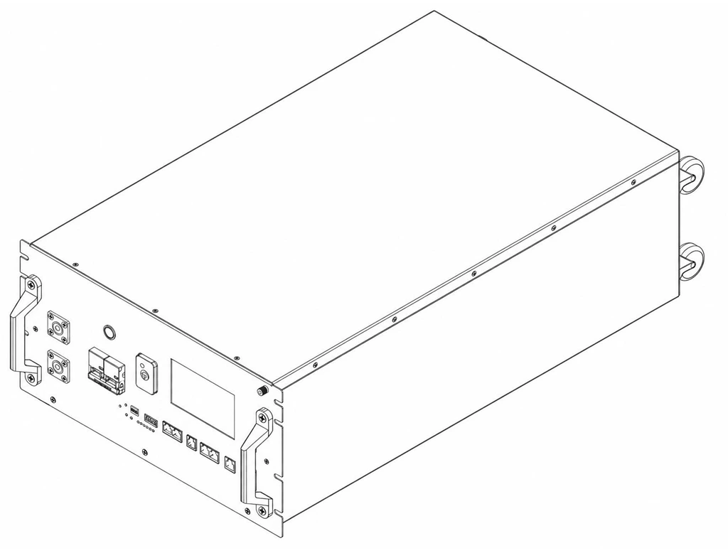
This manual applies to the Gobel Power PowerFable 16 series JKBMS Version (model GP-SR1-16K-JK200) — a 51.2V 314Ah lithium iron phosphate (LiFePO₄) low-voltage energy storage battery. It uses high-performance 314Ah LiFePO₄ cells, features a standard 6U rack-mountable enclosure with casters at the bottom, and is equipped with a high-performance Battery Management System (BMS) that provides comprehensive monitoring and protection of the battery. For the PCBMS Version (model GP-SR1-16K-PC200B), please use its corresponding installation manual.
01PRODUCT OVERVIEW
1.1 · Overview
| Product name | Gobel PowerFable 16 (JKBMS Version) |
| Product model | GP-SR1-16K-JK200 |
| Brand | Gobel Power |
| Product type | 51.2V 314Ah LiFePO₄ low-voltage energy storage battery |
| Rated voltage | 51.2V |
| Rated capacity | 314Ah (approx. 16kWh) |
| Ingress protection | IP21 |
| Installation | Rack · stacked (≤3) · floor (optional wall fixing) |
| Dimensions | See "Product Dimensions" on p. 17 |
| Weight | 120 kg |
01CONTENTS
9 chapters + appendix
01Product Introduction01
02Safety Instructions03
03Transportation & Handling05
04Installation06
05Electrical Connection11
06Operation14
07Product Monitoring15
08Maintenance & Storage16
09Product Specifications17
10Appendix I–V · Contact18
GOBEL POWER
Installation Manual
Features · Interfaces
01PRODUCT FEATURES
1.2 · 8 items
- High-capacity energy storage: rated capacity of 314Ah (approx. 16kWh), meeting the energy storage needs of homes and small commercial & industrial applications
- Safe and reliable: LiFePO₄ cells offer chemically stable, thermally excellent performance
- Intelligent BMS management: real-time monitoring of battery voltage, current, temperature, SOC (state of charge) and other parameters, with multiple protections against over-charge, over-discharge, over-temperature, short circuit and more
- Flexible expansion: supports paralleling of up to 16 batteries for easy capacity expansion; each battery's address is set manually via the 4-bit DIP switch (host = 0, slaves 1 ~ 15)
- Multiple installation methods: 6U standard rack-mount design with casters, supporting rack mounting, stacked installation (up to 3 units) and floor mounting
- Online monitoring: built-in WiFi interface, compatible with the Gobel VRM online monitoring platform, and supports integration with Home Assistant, ioBroker and other platforms
- Mobile APP management: use the JKBMS APP to connect the battery via Bluetooth for status monitoring and configuration
- Standard interfaces: provides RS485A/CAN (inverter), RS485B/RS485C (paralleling / host computer), RS485D (WiFi module), RS232 (reserved) and other communication interfaces, compatible with mainstream inverters
01APPLICATION SCENARIOS
1.3
- Residential PV energy storage systems
- Small commercial and industrial energy storage systems
- Backup power (UPS) systems
- Off-grid energy storage systems
01APPEARANCE & INTERFACES
1.4 · Panel parts on p. 03
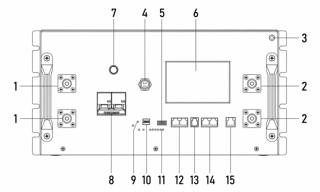
Interface panel — terminals, ports, indicators and controls; the numbers match the parts table on p. 03
GOBEL POWER
Installation Manual
Panel Parts · Safety
| No. | Component | Description |
|---|---|---|
| 1 | Positive terminal | M8 threaded holes, one pair |
| 2 | Negative terminal | M8 threaded holes, one pair |
| 3 | Ground terminal | Grounding connection for the battery system |
| 4 | WiFi interface | Wireless communication interface for the Gobel VRM online monitoring platform, Home Assistant, ioBroker, etc. |
| 5 | Dry contact (DRY) | Dry contact output interface |
| 6 | Display and buttons | Displays battery status information; communication protocol and other parameters can be set on the screen |
| 7 | ON/OFF switch | Turns the battery BMS on or off |
| 8 | Circuit breaker | Controls making/breaking of the battery main circuit |
| 9 | Reset button (RST) | Press and hold to reset the BMS state |
| 10 | DIP switch (ADS) | Sets the battery address for paralleling (host = 0, slaves 1 ~ 15); see Appendix IV (p. 21) |
| 11 | Indicators | Includes RUN (running), ALM (alarm), ON/OFF (switch) and SOC (state of charge) indicators |
| 12 | RS485A/CAN port | Inverter communication interface |
| 13 | RS232 port | Reserved interface (currently not used) |
| 14 | RS485B/RS485C ports | Communication interfaces for battery paralleling; also used to connect a host computer (PC monitoring) |
| 15 | RS485D port | Used together with RS485C when the host connects a WiFi module |
Note: pin definitions of each communication interface are given in Appendix III "Communication Pin Definitions" (p. 19).
02SAFETY INSTRUCTIONS
Read before installation, use and maintenance
Before installing, using and maintaining this product, carefully read and understand the following safety instructions. Failure to comply may result in personal injury, equipment damage or property loss. Do not cover, alter or remove the warning labels and specification nameplate on the product.
2.1 Personnel and Protection Requirements
NOTE — Personnel Requirements
Installation and maintenance operations must be performed by qualified personnel with electrical knowledge. Persons unfamiliar with electrical equipment must not install the product on their own.
WARNING — Personal Protection
- Use insulated tools and wear insulated gloves during operation; remove watches, rings and other metal accessories
- Do not place tools or metal parts on the battery, to prevent terminals from contacting exposed wires or metal objects
- Adjacent live parts should be covered or shielded
- Components may become extremely hot in the event of equipment failure; do not touch them to avoid burns
GOBEL POWER
Installation Manual
Safety Precautions
2.2 Safety Precautions
DANGER — Electric Shock Hazard
This product is an energy storage device; improper operation may cause severe electric shock accidents. Before performing any electrical connection or maintenance, be sure to open the battery circuit breaker and turn off the BMS via the ON/OFF switch.
CAUTION — Battery Safety
- Never short-circuit the positive and negative terminals of the battery; a short circuit produces extremely high current and may cause fire or explosion
- Verify that the battery polarity connections are correct before operation; reversed connection will damage the equipment
- Do not use open flames or spark-generating equipment near the battery
- If the battery enclosure is deformed, leaking or abnormally hot, stop using it immediately and contact technical support
CAUTION — Electrolyte Handling
The electrolyte is harmful to skin and eyes and may be toxic; do not touch it. If electrolyte accidentally contacts eyes or skin, rinse immediately and continuously with clean water for at least 10 minutes and seek medical attention promptly.
DANGER — No Unauthorized Disassembly
No one other than manufacturer-authorized personnel may open, service or disassemble the battery. There are no user-serviceable parts inside; unauthorized disassembly or modification will void the warranty and may cause safety accidents. It is recommended to place warning signs or fences near the product to prevent accidental operation.
CAUTION — Disposal and Recycling
- Batteries that are damaged, swollen or leaking must be taken out of service immediately and stored in a dry, cool, moisture-proof environment away from light; do not repair or disassemble them yourself — contact your installer, dealer or a professional recycling organization
- Waste batteries must not be discarded as household waste; dispose of them at designated recycling points in accordance with local regulations, and remove any privacy-related information from the product before disposal
WARNING — Fire-Fighting Requirements
In the event of a battery fire, only dry-powder fire extinguishers may be used; liquid fire extinguishers are strictly prohibited. Keep the battery away from high-temperature heat sources such as open flames and heaters.
CAUTION — Handling Safety
The product weighs 120 kg; carrying it by a single person by force is prohibited. Handling and moving must be performed with appropriate handling equipment and by multiple people working together. The product is heavy on top and light on the bottom; never lay it on its side or upside down, and take care to prevent the equipment from tipping over during movement, which could cause personal injury. See "Transportation & Handling" on p. 05.
GOBEL POWER
Installation Manual
Transportation & Handling
03TRANSPORTATION & HANDLING
120 kg · top-heavy
3.1 Transportation Requirements
- During transportation, protect the product from severe vibration, shock and crushing; avoid direct sunlight, rain and moisture, and take rain-proof, moisture-proof and sun-proof measures
- Smoking is strictly prohibited in transportation, loading and unloading areas; without permission, freight personnel must not open the battery packaging on their own
- Lithium-ion batteries are Class 9 dangerous goods (UN3480); cross-border sea, land and air transport must comply with the applicable dangerous goods transport regulations, and dangerous goods labels must be affixed as required
- If the battery emits an odor, leaks, smokes, catches fire or shows any other abnormality before transportation, transportation is strictly prohibited
- Transportation operations must be performed by trained professionals; handlers must wear protective gloves and safety shoes
- Do not remove the transportation packaging before the product arrives at the installation site
3.2 Handling Methods
3.2.1 Manual Handling
- The product weighs 120 kg; carrying it by a single person by force is prohibited. Before handling, confirm that all personnel are in good physical condition, wear anti-slip gloves, safety shoes and other protective gear, and watch out for sharp metal panels and heavy objects
- Clear the handling route and confirm the floor is safe before moving; slow down when passing ramps, narrow spaces and stairs, and assign dedicated personnel to assist
- The product is heavy on top and light on the bottom; laying it on its side, upside down or moving it without securing it is prohibited. Take measures to prevent tipping during movement
- Only push or lift the product by its designated handles or bottom edge; never grip components installed inside the equipment
- For short-distance movement on level ground, the bottom casters may be used, with multiple people pushing together; lock the casters once the product is in position
- When carrying, stay close to the equipment, bend your knees and lift smoothly, using leg strength rather than your back; do not jerk or twist your body. When turning, move your feet instead of twisting your waist
- Move the equipment smoothly at a constant speed and lift and set it down gently, to prevent collision, dropping, scratching or damage to components and cables
- After handling, confirm that the equipment is placed stably to prevent it from tipping over and injuring people
3.2.2 Using Handling Equipment
- When using forklifts or other handling equipment, operation must be performed by certified professionals in compliance with the equipment's operating requirements; unrelated personnel must stay at least 2m away from the work area, standing or riding on the forklift or its load is prohibited, and overloading is prohibited
- The rated load of the handling equipment should be more than twice the product weight (this product weighs 120 kg, i.e. more than 240 kg), and the fork arm length should be no less than the product depth
- Control travel speed and avoid sharp turns; before reversing, confirm the area behind is clear, and assign dedicated personnel to direct operations in narrow spaces
- Working on slopes with a gradient ≥5° is prohibited; slow down on uneven ground
- Tilting or inverting the product during handling is prohibited; if tilting is unavoidable, return it upright as soon as possible and let it stand for 2 hours before powering on
GOBEL POWER
Installation Manual
Pre-Installation
04INSTALLATION
Rack · stacked · floor
4.1 Pre-Installation Preparation · 4.1.1 Installation Environment Requirements
- Floor/rack: the installation floor should be level and solid with sufficient load-bearing capacity (the product weighs 120 kg); when using rack mounting, the rack must be strong enough to reliably bear the total weight of the batteries installed
- Ventilation: the installation site should be well ventilated to avoid heat accumulation; do not block the equipment's vents or heat-dissipation structures, and keep away from equipment air outlets
- Environmental conditions: dry and clean, free of corrosive gases or dust; ambient temperature 0°C ~ 50°C, relative humidity not exceeding 95% RH (non-condensing); the recommended installation altitude is no more than 3000m
- Safety clearances: keep away from flammable and explosive materials and water sources; keep away from heat sources, open flames and high-temperature objects. Do not install or operate the equipment in environments containing flammable or explosive gases or fumes, and do not store flammable or explosive materials around the equipment
- Waterproofing: this product has an IP21 ingress protection rating and is not waterproof. It must not be installed outdoors in exposed locations; exposure to rain, water splash or snow accumulation is strictly prohibited. Do not install it in locations that may be flooded, and keep it away from liquids and areas prone to condensation or water seepage
- Corrosive environments: avoid magnetic dust, volatile or corrosive gases, organic solvents, conductive metal dust and salt-spray environments
- Electromagnetic and vibration: avoid locations with strong vibration, noise and electromagnetic interference
- Others: do not install the equipment on moving carriers such as ships, trains or automobiles; the installation location should be away from children and daily living and working areas
To ensure heat dissipation and space for maintenance operations, maintain sufficient clearance between the battery and walls or other equipment:
- Distance from both sides of the battery to walls ≥ 100mm
- Distance from the top of the battery to obstacles above ≥ 300mm
- Reserve at least 800mm of operating space in front of the battery
CAUTION
Before installation and power-on, clear dust and iron filings from the installation area; before installation, confirm that the site (or rack) has sufficient load-bearing capacity and take anti-static measures; do not install the equipment in enclosed, poorly ventilated locations without fire-fighting facilities, or in locations inaccessible to fire fighters.
GOBEL POWER
Installation Manual
Tools & Torque
4.1.2 Tool and Torque Requirements
Prepare the following tools and instruments before installation:
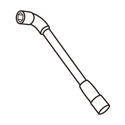
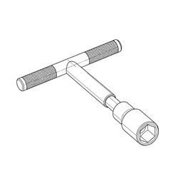
Socket / torque wrench
Tighten the M8 positive and negative power terminals

Adjustable wrench
Tighten expansion bolt nuts
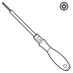
Phillips screwdriver
Install rack ears and wall fixing brackets
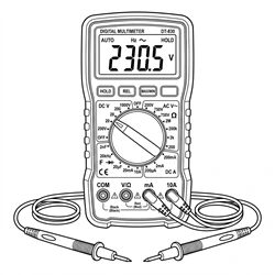
Multimeter
Measure terminal voltage

Electric drill
Drill wall holes for floor mounting

Hammer
Drive expansion bolts into the wall
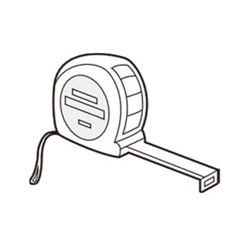
Tape measure
Measure installation hole distances

Marker pen
Mark drilling positions
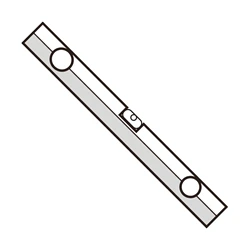
Spirit level
Confirm the equipment is installed level

RJ45 crimping tool
Make custom communication/parallel network cables
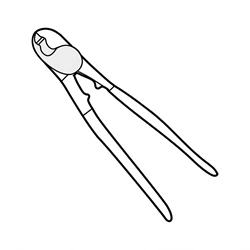
Crimping tool
Make custom power cables (if needed)

Insulated gloves
Operation protection
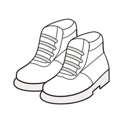
Insulated shoes
Operation protection
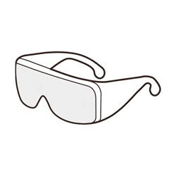
Safety goggles
Protection for drilling and other work (recommended)
+
Windows PC
For host software protocol setting
+
Smartphone
For JKBMS APP configuration (Bluetooth)
Torque Requirements
When making electrical connections, tighten the screws to the torque values specified below:
| Screw Size | Torque Requirement |
|---|---|
| M6 | 8N·m |
| M8 | 15N·m |
| M10 | 15 ~ 20N·m |
NOTE — Torque Notes
- The positive and negative power terminals of this product are M8 size; tighten them to a torque of 15N·m
- The torque values apply to standard screws under conventional assembly conditions; adjust as appropriate for special conditions such as high vibration or harsh environments
- Use a calibrated torque wrench to avoid over-tightening or under-tightening the screws
GOBEL POWER
Installation Manual
Unpacking & Inspection
4.2 Unpacking and Inspection · 4.2.1 Parts List
After unpacking, check the product and accessories against the table below to confirm that all parts are complete and in good condition.
| No. | Item | Specification / Qty | Photo |
|---|---|---|---|
| 01 | Gobel PowerFable 16 energy storage battery | 51.2V 314Ah, 1 unit | |
| 02 | Positive power cable | 50mm², 1m, M8 terminals on both ends, 1 pc | 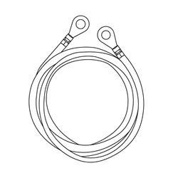 |
| 03 | Negative power cable | 50mm², 1m, M8 terminals on both ends, 1 pc | 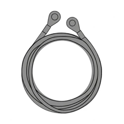 |
| 04 | Communication network cable | RJ45 on both ends, symmetric wiring, 1 pc (parallel cable or inverter communication cable) | 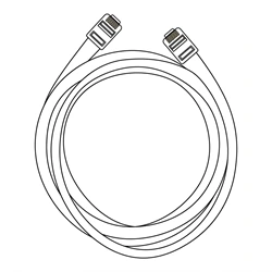 |
| 05 | RS485-USB communication cable | 1 pc (connects to the computer host software) | 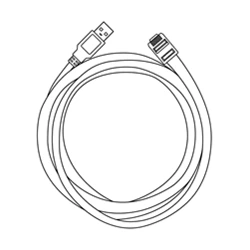 |
| 06 | Short network cable | RJ45 on both ends, 1 pc (connects the RS485C and RS485D ports) | 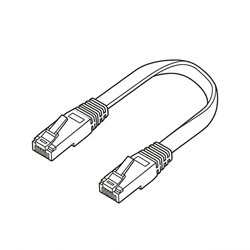 |
| 07 | Rack mounting ears (left/right) | 1 left ear and 1 right ear (rack fixing and wall fixing) | 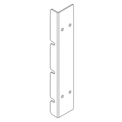 |
| 08 | Wall fixing bracket | 2 pcs (wall fixing in floor mounting) | 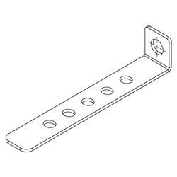 |
| 09 | Expansion bolt | 2 pcs | 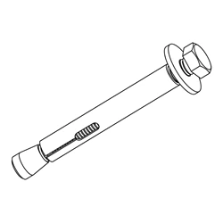 |
4.2.2 Unpacking Inspection Procedure
After receiving the product, perform the unpacking inspection as follows:
- Remove the energy storage battery (01) from its packaging and check whether the outer packaging and product appearance are intact.
- Check the product and accessories against the parts list above for missing or damaged items.
- Power on via the panel ON/OFF switch, and check whether the display and indicators show normal readings.
- Set the circuit breaker to the ON position, and use a multimeter to measure the voltage across the battery positive terminal and negative terminal; the normal voltage should be between 40V ~ 58V.
- If all checks are normal, proceed to the next installation step.
CAUTION
If the product appearance is damaged, accessories are missing or the voltage is abnormal, do not continue installation; contact Gobel Power technical support promptly.
GOBEL POWER
Installation Manual
Installation Steps
NOTE — Unpacking Tips
- Do not remove the transportation packaging in advance before the product arrives at the installation site; handle with care when unpacking to avoid scratching the equipment
- Before unpacking, check whether the outer packaging is damaged and whether the shock indicator has been triggered; if triggered, transportation damage cannot be ruled out
- Clean all parts before installation; prevent collision and scratching during handling and storage, and take moisture-proof and rust-proof measures
- The system should be installed and commissioned within 6 months of delivery; long-term idle storage accelerates battery capacity degradation
4.3 Installation Procedures
This product features a 6U standard rack-mount structure with casters at the bottom, and supports three installation methods: rack mounting, stacked installation and floor mounting (optional wall fixing). Choose one method according to the actual site conditions.
- Open the circuit breaker of the energy storage battery (01) and power it off via the ON/OFF switch.
- Select one of the installation methods below according to the site conditions.
4.3.1 Rack Mounting
- Install the left/right rack ears (07) onto the mounting holes on both sides of the battery with screws, taking care to distinguish the orientation of the left and right ears.
- With multiple people working together (or using handling equipment), push the battery into the predetermined slot of a standard 19-inch rack.
- Pass screws through the mounting holes in the left and right ears to fasten the battery securely to the front and rear posts of the rack.
Rack mounting ears (left/right)
CAUTION — Rack Load-Bearing Requirements
The rack holding the battery must be strong enough to reliably bear the battery weight (a single battery weighs 120 kg). When multiple batteries are installed in the same rack, calculate the load-bearing capacity of the rack and floor slab based on the total weight of the batteries in the rack, and ensure the rack itself is stable and does not wobble.
4.3.2 Stacked Installation
- Place the bottom battery on a flat, solid, level floor.
- Stack the remaining batteries one by one on top of the bottom battery, keeping them aligned vertically and placed steadily.
CAUTION — Stacking Limit
The maximum number of stacked units must not exceed 3. After stacking, confirm that each battery is stable and does not wobble; if necessary, refer to Section 4.3.3 "Floor Mounting" to secure the equipment to the wall to prevent tipping.
GOBEL POWER
Installation Manual
Floor Mounting · Wall Fixing
4.3.3 Floor Mounting
- Use the bottom casters to move the battery to the predetermined installation position, and lock the casters to prevent movement.
- (Optional) To secure the battery to the wall, follow these steps:
- Install the left/right rack ears (07) onto both sides of the battery.
- Install the wall fixing brackets (08) onto the left and right ears.
- Use the marker pen to mark the wall through the holes in the wall fixing bracket, drill holes at the marked positions with the electric drill, insert the expansion bolts (09) into the drilled holes, and finally tighten the nuts with a wrench to secure the brackets to the wall.
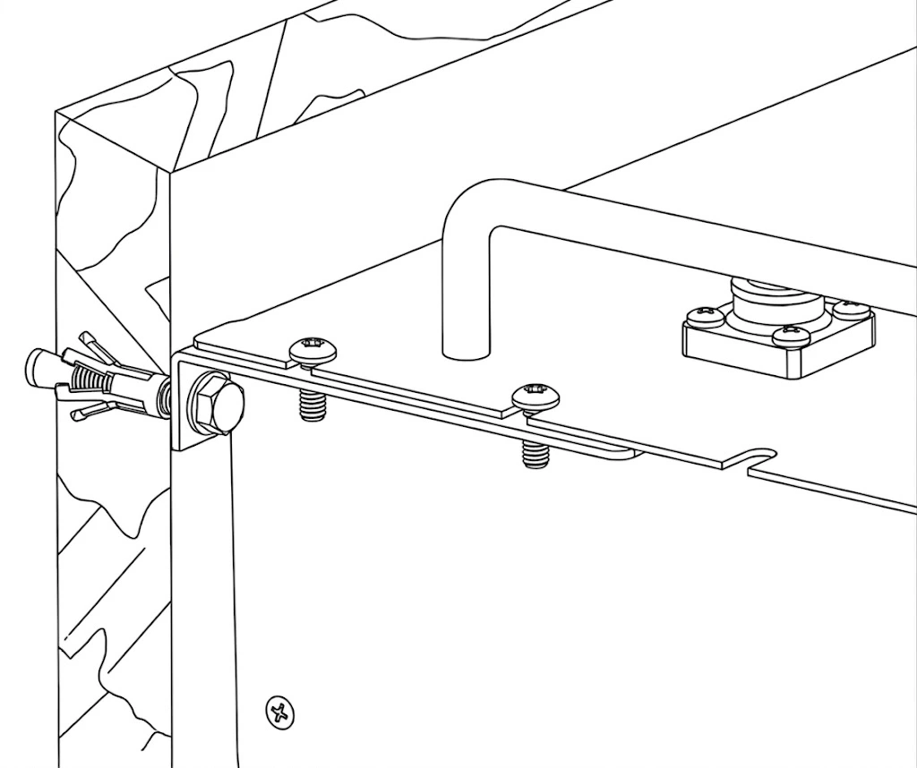
Wall fixing bracket installation
Wall fixing bracket (08)
CAUTION
Pay attention to floor evenness when moving the battery and avoid excessive tilt angles. The battery weighs 120 kg; be sure to move it safely to prevent it from tipping over and injuring people. Before drilling into the wall, confirm there are no water, electricity or gas pipes inside; when drilling, prevent dust from entering the battery, and clean up the debris after drilling.
CAUTION — Installation Discipline
- Installation must strictly follow this manual and the design requirements; unauthorized changes to installation steps or technical parameters are prohibited
- During installation and wiring, keep all switches in the OFF position; working on live equipment is strictly prohibited
- All screws and fasteners must be tightened securely; when drilling, prevent dust from entering the battery, avoid pipes inside walls or underground, and clean up the debris after drilling
4.4 Post-Installation Inspection
After installation is complete, confirm the following items are normal:
- The battery exterior is intact, with no deformation, dents or scratches
- The equipment is placed securely: for rack mounting, the left/right ear screws are tightened; for stacked installation, all units are aligned and stable; for floor mounting, the casters are locked (and the wall fixing brackets are secure if wall-fixed)
- Surrounding passages are clear and free of flammable and explosive materials
- Warning labels and the specification nameplate are complete and legible
- On-site fire-fighting equipment is in place and compliant
GOBEL POWER
Installation Manual
Electrical Safety · Preparation
05ELECTRICAL CONNECTION
Confirm the inverter is off and disconnected before wiring
5.1 Safety Precautions
WARNING — Wiring Requirements
This product supports parallel connection only; series connection is strictly prohibited. A maximum of 16 units can be connected in parallel. Series connection may cause equipment damage or safety hazards.
WARNING — Electrical Safety Precautions
- Terminals may still carry residual voltage after the battery is powered off. Before wiring, wait at least 10 minutes and use a multimeter to confirm that no voltage is present
- Never connect the battery directly to the AC grid or to PV (photovoltaic) DC lines; the battery may only be connected to matching power conversion equipment such as an inverter
- Do not use faulty power conversion equipment (such as an inverter) or one that is not matched to the battery; before connection, confirm that the battery system parameters are fully compatible with the connected equipment
- Do not perform electrical connections during sandstorms or when the ambient relative humidity exceeds 95%
- Wiring must be performed by qualified personnel with electrical knowledge, wearing protective equipment as required in Chapter 2
5.2 Connection Preparation · 5.2.1 Cable Preparation
Before connection, confirm that the following cables and parts are ready:
- Positive power cable (02): 50mm², 1m, M8 terminals on both ends
- Negative power cable (03): 50mm², 1m, M8 terminals on both ends
- Communication network cable (04): RJ45 on both ends, symmetrically wired; can be used as a parallel communication cable or an inverter communication cable
- RS485-USB communication cable (05): used to connect a Windows PC for host software monitoring and protocol configuration
Also confirm that the inverter and other equipment have been installed in place, and shut down and de-energize the inverter. Refer to the battery connection sections of the inverter manual as well.
GOBEL POWER
Installation Manual
DIP Settings · Cable Connection
5.2.2 Battery DIP Switch Settings
If there is only one battery, it is the host; set its DIP switches to address 0 (all four switches OFF). If multiple batteries are connected in parallel, select one as the host (address 0) and set the others to slave addresses 1 ~ 15; for the DIP switch settings of each address, refer to Appendix IV "DIP Switch Settings Table" (p. 21).
5.3 Cable Connection
5.3.1 Grounding Connection
- Use a grounding cable to reliably connect the battery ground terminal to earth. The grounding resistance shall be less than 1Ω. Follow local electrical codes and the inverter's requirements for the grounding method
- Ensure that an overvoltage protection device is installed at the site where the system is located
5.3.2 Power Cable Connection
Connect one end of the positive power cable (02) to the battery positive terminal (M8, either free terminal of the pair), and the other end to the inverter's positive battery input. Connect one end of the negative power cable (03) to the battery negative terminal (M8, either free terminal of the pair), and the other end to the inverter's negative battery input. Tighten the terminal screws to the specified torque (see Section 4.1.2): 15N·m for M8.
CAUTION
Make sure the positive and negative terminals are correctly matched; reverse connection will cause severe equipment damage.
Note · Cable routing: do not pull or strain the cables. Leave sufficient bending space for the cables and use appropriate fasteners to reduce cable stress.
5.3.3 Communication Cable Connection
Connect one end of the communication network cable (04) to the RS485A/CAN port of the host battery, and the other end to the inverter's BMS communication interface (whether RS485 or CAN protocol is used depends on the inverter manual and must match the battery's protocol settings). For communication wiring when multiple batteries are connected in parallel, refer to Section 5.4 "Multi-Pack Parallel Connection".
CAUTION
Verify that the pin definitions of the inverter's BMS communication interface match those of the battery's RS485A/CAN port. The communication network cable supplied with this product is symmetrically wired on both ends. If the pin definitions of the inverter and the battery differ, you need to make a communication cable with the corresponding wiring sequence using an RJ45 crimping tool, or purchase an adapter cable from the inverter manufacturer (e.g., for Victron inverters).
Note: for the pin definitions of each communication interface, see Appendix III "Communication Pin Definitions" (p. 19).
GOBEL POWER
Installation Manual
Parallel Connection
5.4 Multi-Pack Parallel Connection
CAUTION
Never connect batteries of different models or specifications in parallel. This product supports a maximum of 16 units in parallel. When connecting multiple batteries, route the cables along the designated paths; do not change the wiring layout arbitrarily.
5.4.1 Parallel Power Connection
If multiple batteries are used in parallel, they must first be paralleled and then connected to the inverter. Each battery has one pair of positive terminals and one pair of negative terminals (M8), and each terminal carries a maximum current of 200A, and the maximum continuous current of a single battery is 150A. Two cases apply:
- Case 1: if the inverter input/output current is less than 200A, use power cables to interconnect the positive and negative terminals of adjacent batteries, and then connect the batteries at both ends to the inverter.
- Case 2: if the inverter input/output current is greater than 200A, connect the positive and negative terminals of each battery to busbars, and then connect the busbars to the inverter.
Note: for connection diagrams, see Appendix V "Battery-Inverter Connection Diagrams" (p. 22).
5.4.2 Parallel Communication Connection
When multiple batteries are connected in parallel, use parallel communication cables to daisy-chain the RS485B and RS485C ports of the batteries: connect the RS485B of the first battery to the RS485C of the second battery, the RS485B of the second battery to the RS485C of the third battery, and so on.
Note: before wiring the parallel communication cables, complete the DIP switch settings for the host and slaves (Appendix IV, p. 21).
5.5 Post-Connection Inspection
After all cables are connected, check each item in turn:
- After completing each connection, verify that it is correct and secure, with no looseness or poor contact; all bolts, screws, and other fasteners are fully tightened
- Positive and negative power cables have correct polarity, and the terminals are secure and reliable
- Prevent terminals from contacting exposed wires or metal objects; adjacent live parts should be covered
- Remove foreign objects around the equipment, especially metal debris, to prevent short circuits
GOBEL POWER
Installation Manual
Operation · Power On
06OPERATION
Pre-start checks · Protocol · Power on
6.1 Pre-Power-On Checks
CAUTION — Before Power On
- All items of Section 5.5 "Post-Connection Inspection" have been confirmed correct
- The work area is cleared; unauthorized personnel and animals are kept away from the equipment
6.2 Inverter Communication Protocol Settings
When multiple batteries are connected in parallel, only the host battery's communication protocol needs to be set; slaves require no configuration. Use any one of the following three methods:
- Set on the screen: enter the settings menu via the host battery's display and buttons and select the communication protocol that matches the inverter.
- Set via PC host software: use the RS485-USB communication cable (05) to connect a Windows PC to the host battery, and select the communication protocol that matches the inverter in the host software on the PC.
For detailed host software operation, refer to the "JKBMS Software User Manual" in the Reference Documents (p. 22).
- Set via mobile APP: connect a mobile phone to the host battery via Bluetooth, and select the communication protocol that matches the inverter in the JKBMS APP.
Note · WiFi configuration: for the battery's WiFi configuration and access to the online monitoring platform, refer to the "WiFi User Manual".
Note · Inverter compatibility: before setting the communication protocol, confirm that the brand and model of the inverter are compatible with the battery. For the list of verified compatible inverters, refer to the "Inverter Compatibility List" in the Reference Documents (p. 22).
6.3 Power-On
Power on in the following sequence: BMS power-on (ON/OFF switch) → Wait → Circuit breaker ON → Inverter power-on.
- Check the power and communication connections to ensure all cables are firmly connected with no looseness.
- Press the ON/OFF switch on all batteries to power on (BMS ON), and wait for the battery system to complete self-check, with the display showing normal status and no alarms.
- Switch the circuit breaker of all batteries to the ON position.
- Turn on the inverter's power switch.
- Set the battery type to lithium battery in the inverter.
- Check the battery information displayed in the inverter to confirm that data has been correctly retrieved from the battery BMS (e.g., battery voltage, battery SOC, temperature).
- If the inverter reads the data correctly, the installation is complete and charge/discharge testing can be performed.
WARNING — Power-On Sequence
Do not turn on the inverter before or simultaneously with the circuit breaker, and do not close the circuit breaker without the waiting step; otherwise, a large inrush current may occur, causing equipment damage or triggering protection.
Tip: if the inverter cannot read battery data after power-on, check whether the communication cables are properly connected and whether the communication protocol is set correctly. For more common fault handling, see Appendix I (p. 18).
GOBEL POWER
Installation Manual
Power Off · Monitoring
6.4 Power-Off
Power off in the following sequence: Inverter OFF → Wait → Circuit breaker OFF → BMS power-off (ON/OFF switch).
- Shut down the inverter and its loads, and wait for the inverter to stop working completely.
- Switch the circuit breaker of all batteries to the OFF position.
- Press the ON/OFF switch to turn off the BMS of each battery.
CAUTION
Terminals may still carry residual voltage after power-off; do not touch the terminals immediately. Before performing maintenance, follow Section 8.1 "Maintenance Safety Precautions".
07PRODUCT MONITORING
Panel indicators · Host software · Remote
7.1 Panel Status Indicators
The battery's operating status can be viewed via the panel indicators and display:
| Component | Description |
|---|---|
| Switch indicator (ON/OFF) | Indicates the battery switch status |
| Run indicator (RUN) | Indicates the battery operating status |
| Alarm indicator (ALM) | Lights up when the battery has a fault or alarm |
| SOC indicators | Indicate the battery state of charge |
| Display and buttons | Display battery status information; parameters can be viewed and set on the screen |
When the alarm indicator (ALM) lights up, promptly investigate the cause of the fault. If it cannot be resolved, contact Gobel Power technical support. For common fault handling, see Appendix I (p. 18).
7.2 Host Software and Remote Monitoring
This product supports multiple monitoring methods:
- PC host software monitoring: use the RS485-USB communication cable (05) to connect a Windows PC to the battery, and run the battery host software on the PC to view operating status such as battery voltage, current, temperature, and SOC.
- Mobile APP monitoring: connect a mobile phone to the battery via Bluetooth, view the battery status via the JKBMS APP, and configure or upgrade the battery in the APP.
- WiFi online monitoring: after the battery's built-in WiFi interface connects to the network, it is compatible with the Gobel VRM online monitoring platform and supports integration with platforms such as Home Assistant and ioBroker for remote monitoring. For WiFi configuration, refer to the "WiFi User Manual".
Note: for detailed host software operation, refer to the "JKBMS Software User Manual" in the Reference Documents (p. 22).
GOBEL POWER
Installation Manual
Maintenance & Storage
08MAINTENANCE & STORAGE
Fully power off before maintenance
8.1 Maintenance Safety Precautions
- Before maintenance, the battery must be completely de-energized (disconnect both the grid and the battery side), following the principle of "de-energize → prevent unintended re-closing → verify no voltage → grounding and short-circuit protection → cover adjacent live parts"
- Hang a "Do Not Close" warning tag on the switch position to prevent unintended power restoration
- Before maintenance, disconnect all battery terminals and circuit connectors, and install protective caps on the terminals; use insulated tools and never wear jewelry, watches, or other metal accessories
8.2 Routine Maintenance Requirements
- When replacing parts, always use spare parts of the same type and specification
- Do not spray paint on any internal or external parts of the battery, and do not clean the battery with cleaning solvents
- If any abnormality is found, contact the supplier within 24 hours
- During daily use, keep the battery SOC above 5%, and recharge within 48 hours after a full discharge to avoid over-discharge
8.3 Post-Maintenance Requirements
- After maintenance, clear all tools and materials and confirm that no metal foreign objects are left inside or on top of the battery
- Confirm that terminal protective caps, guards, etc., are all restored in place before re-energizing
8.4 Long-Term Storage
If the battery will not be used for an extended period, store and maintain it as follows:
- Fully charge the battery, then switch off the circuit breaker and the ON/OFF switch (BMS off)
- Check the battery voltage at least every 3 months. If the voltage is below 51V, recharge promptly
- Store the battery in a dry, clean, well-ventilated indoor location, away from direct sunlight and rain, and away from high-temperature heat sources, open flames, and flammable or explosive materials
- During storage, the battery should be completely disconnected from external equipment, and all indicators should be off
- The floor of the storage area should be level and solid, and qualified fire protection facilities (e.g., dry powder extinguishers, fire sand) should be provided
- Handle with care during transport and storage; dropping, collision, tipping, side placement, and tilting are prohibited
DANGER
Battery damage caused by failure to recharge in time is not covered by the warranty. Long-term storage without recharging will over-discharge the battery, causing irreversible capacity loss or even scrapping the battery.
GOBEL POWER
Installation Manual
Specifications
09PRODUCT SPECIFICATIONS
9.1 · Technical parameters
9.1 Technical Parameters
| Item | Parameter |
|---|---|
| Product name | Gobel PowerFable 16 (JKBMS Version) |
| Product model | GP-SR1-16K-JK200 |
| Brand | Gobel Power |
| Product type | 51.2V 314Ah LiFePO₄ low-voltage energy storage battery |
| Main parameters | |
| Cell type | LiFePO₄ (lithium iron phosphate) |
| Rated capacity | 314Ah [1] |
| Parallel expansion | Up to 16 units in parallel [2]; series connection strictly prohibited |
| Nominal voltage | 51.2V |
| Operating voltage | 44.8V ~ 58.4V |
| Nominal energy | Approx. 16kWh |
| Usable energy | 16kWh [1] |
| Maximum output power | 7.68kW |
| Charge current [3] | Max. continuous 150A; peak 200A (25 seconds) |
| Discharge current [3] | Max. continuous 150A; peak 200A (25 seconds) |
| Active balancing | Yes |
| Other parameters | |
| Maximum depth of discharge | 100% DOD |
| Dimensions (W×H×D) | 482.6 × 241.3 × 773mm |
| Weight | 120kg |
| Display | Screen (SOC, alarm, total voltage, current, inverter protocol) |
| Ingress protection rating | IP21 |
| Operating temperature | 0°C ~ 50°C |
| Storage temperature | 0°C ~ 35°C |
| Relative humidity | ≤95% RH (non-condensing) |
| Altitude | ≤3000m |
| Cycle life | ≥8000 cycles (25°C±2°C, 70% EOL) |
| Electrical isolation protection | Built-in circuit breaker |
| Installation | Rack mounting / stacking (≤3 layers) / floor mounting (optional wall fixing), with casters on the bottom |
| Communication interfaces | RS485A/CAN (inverter), RS485B/RS485C (parallel / host computer), RS485D (WiFi module), RS232 (reserved), WiFi (online monitoring), dry contact (DRY) |
| Energy throughput | 50MWh [4] |
[1] Test conditions: 25°C±2°C, beginning of life (BOL), 0.5C charge / 0.5C discharge, 100% DOD.
[2] Addresses are set manually via the 4-bit DIP switch: host = 0, slaves 1 ~ 15 (see Appendix IV).
[3] Current is affected by temperature and SOC.
[4] Energy throughput refers to the total cumulative charge and discharge energy over the battery's entire service life.
GOBEL POWER
Installation Manual
Dimensions · Troubleshooting · Emergency
10APPENDIX
9.2 Dimensions · Appendices I–II
9.2 Product Dimensions Diagram
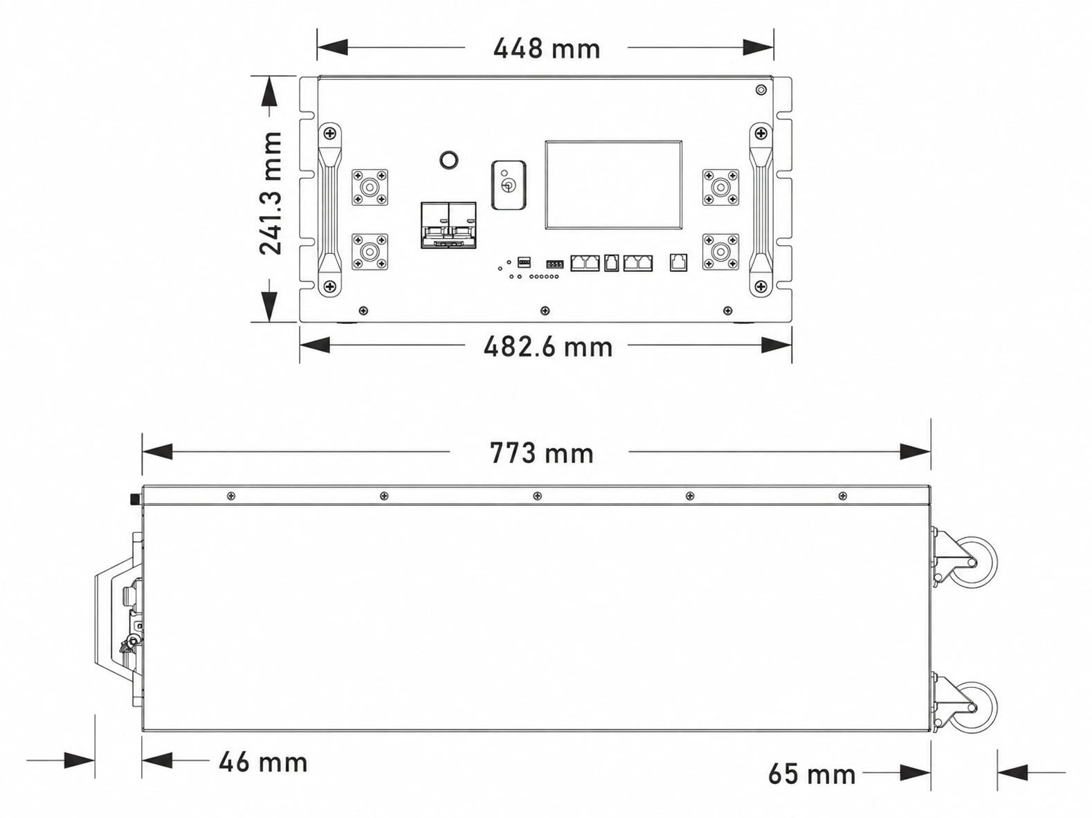
GP-SR1-16K-JK200 product dimensions (unit: mm)
Appendix I Common Faults and Troubleshooting
| Symptom | Possible Cause | Remedy |
|---|---|---|
| Inverter cannot read battery data | Loose or open communication cable connection; mismatched pin definitions on both ends; incorrect communication protocol settings | Check the communication cable connections; verify the pin definitions on both ends (Appendix III, p. 19); reconfigure the communication protocol (Section 6.2) |
| Abnormal terminal voltage measured at unboxing (below 40V or above 58V) | State of charge too low or product abnormality | Do not proceed with installation or use; contact Gobel Power technical support |
| Alarm indicator (ALM) lights up | Battery fault or alarm | Stop use and investigate the cause; contact Gobel Power technical support if necessary |
| Battery enclosure deformed, leaking, or abnormally hot | Internal battery abnormality | Stop use immediately and contact technical support; see Appendix II for handling procedures |
| WiFi or mobile APP cannot connect to the battery | WiFi not configured or misconfigured | Reconfigure as described in the "WiFi User Manual" |
| Voltage below 51V after long-term storage | Self-discharge during storage | Recharge promptly before returning to service (Section 8.4) |
Appendix II Emergency Handling
DANGER
In emergencies such as electric shock, fire, or electrolyte leakage, ensure personal safety first, evacuate personnel promptly, and call the appropriate emergency numbers. Do not operate damaged equipment without professional inspection and qualified testing.
GOBEL POWER
Installation Manual
Emergency · Pin Definitions
Appendix II Emergency Handling (cont.)
Electric Shock
- Cut off the power immediately, provided your own safety is ensured
- Use an insulated object to separate the victim from the power source, administer first aid including cardiopulmonary resuscitation (CPR), and immediately call the emergency number
- Preserve the accident scene for investigation and evidence collection
- After the accident, the system must be inspected by professionals and may only be returned to service after repair or replacement and passing testing
Fire or Explosion Risk
- Evacuate the area immediately and call the fire department; stay away from smoke produced by burning. Only dry powder extinguishers may be used to fight the fire; liquid extinguishers are strictly prohibited
- Cut off the upstream power supply, provided your own safety is ensured, and wear respiratory protective equipment
- Isolate the accident area where it is safe to do so, preventing unauthorized personnel from entering; post-incident handling must be completed by professionals
Electrolyte Leakage and Chemical Hazards
- In the event of electrolyte leakage, evacuate personnel immediately and notify the relevant personnel; the leaked material must be safely collected and disposed of by professionals
- Burning or damaged batteries may release toxic gases; evacuate to a safe area immediately. If personnel are exposed or injured, seek medical attention immediately
- When handling leaked material, wear respiratory protective equipment, protective clothing, and other safety gear
Mechanical Injury
- If the equipment tips over, the battery falls, or parts come loose, cut off the power immediately and stop the system
- If anyone is injured, administer first aid such as stopping bleeding and bandaging, and immediately call the emergency number
- If abnormalities such as odor, damage, smoking, or fire are observed, evacuate immediately and raise the alarm; the abnormal battery should be moved by professionals to an open, safe area, left undisturbed for at least 1 hour, and its temperature monitored
Appendix III Product Communication Pin Definitions
RS485A Port
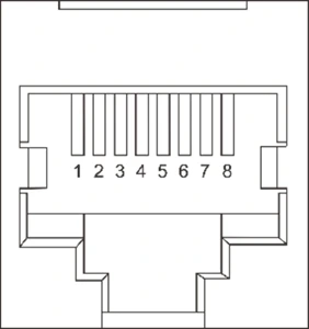
| Pin | Definition |
|---|---|
| 1 | B |
| 2 | A |
| 3 | GND |
| 4 | NC |
| 5 | NC |
| 6 | GND |
| 7 | A |
| 8 | B |
CAN Port
| Pin | Definition |
|---|---|
| 1 | NC |
| 2 | NC |
| 3 | NC |
| 4 | CAN-H |
| 5 | CAN-L |
| 6 | NC |
| 7 | GND |
| 8 | NC |
GOBEL POWER
Installation Manual
Emergency (cont.) · Pin Definitions
Appendix II Emergency Handling (cont.)
Natural Disasters
- In the event of natural disasters such as earthquakes, typhoons, floods, or wildfires, cut off the power immediately and stop the system
- If the system is flooded or submerged, do not touch it and stay away from the waterlogged area. Flooded batteries must not be used again; contact a professional recycling agency for scrapping
- Before a wildfire approaches, a firebreak may be established around the system, and fire equipment such as extinguishers and fire sand should be prepared
- After the disaster, professionals must inspect the support structure, electrical connections, and other components; the system may only be reused after repair or replacement and passing testing
Appendix III Product Communication Pin Definitions (cont.)
RS485B / RS485C Ports
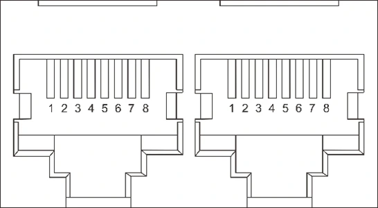
| Pin | Definition |
|---|---|
| 1 | B |
| 2 | A |
| 3 | GND |
| 4 | NC |
| 5 | NC |
| 6 | GND |
| 7 | A |
| 8 | B |
Appendix IV DIP Switch Settings Table
The address range of this product's DIP switches (ADS) is 0 ~ 15: address 0 (all switches OFF) is the host, and addresses 1 ~ 15 are slaves. In a parallel system the host is the battery set to address 0, and at most 16 batteries can be connected in parallel. The complete settings table is on the next page.
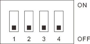
4-bit DIP switch (ADS) on the panel — #1 ~ #4
GOBEL POWER
Installation Manual
DIP Switch Settings Table
Appendix IV DIP Switch Settings Table (cont.)
Address 0 – 15 · 0 = Host
| Address | #1 | #2 | #3 | #4 | Description |
|---|---|---|---|---|---|
| 0 | OFF | OFF | OFF | OFF | Host (also used when the battery operates alone) |
| 1 | ON | OFF | OFF | OFF | Slave |
| 2 | OFF | ON | OFF | OFF | Slave |
| 3 | ON | ON | OFF | OFF | Slave |
| 4 | OFF | OFF | ON | OFF | Slave |
| 5 | ON | OFF | ON | OFF | Slave |
| 6 | OFF | ON | ON | OFF | Slave |
| 7 | ON | ON | ON | OFF | Slave |
| 8 | OFF | OFF | OFF | ON | Slave |
| 9 | ON | OFF | OFF | ON | Slave |
| 10 | OFF | ON | OFF | ON | Slave |
| 11 | ON | ON | OFF | ON | Slave |
| 12 | OFF | OFF | ON | ON | Slave |
| 13 | ON | OFF | ON | ON | Slave |
| 14 | OFF | ON | ON | ON | Slave |
| 15 | ON | ON | ON | ON | Slave |
Shaded row (address 0) — host: all four DIP switches are OFF. Addresses 1 ~ 15 are slaves, set manually with switches #1 ~ #4. A parallel system supports at most 16 batteries: one host (address 0) plus up to 15 slaves.
GOBEL POWER
Installation Manual
Diagrams · Reference · Contact
Appendix V Battery-Inverter Connection Diagrams
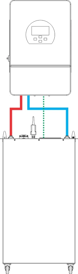
Single Battery-to-Inverter Connection
Note: solid lines represent the positive and negative power cables; dotted lines represent the communication cable.
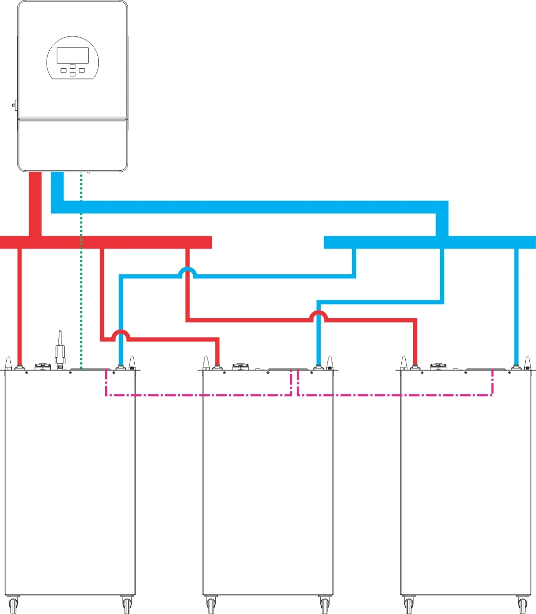
Multiple Batteries-to-Inverter Connection
Note: solid lines represent the positive power cables, negative power cables, and busbar; dotted lines represent the inverter communication cables; dash-dotted lines (-.-.-) represent the parallel communication cables between batteries.
Reference Documents
In addition to this manual, refer to the following companion documents as needed:
| Document Name | Description |
|---|---|
| WiFi User Manual | Battery WiFi configuration and integration with online monitoring platforms such as Gobel VRM, Home Assistant, and ioBroker |
| JKBMS Software User Manual | Installation and detailed operating instructions for the PC host software |
| Inverter Compatibility List | List of verified compatible inverter brands and models |
CONTACT
If you encounter a fault that cannot be resolved or need technical support, contact Gobel Power:
www.gobelpower.com
[email protected]